Fruit Ripening Automation
The Automated Fruit Ripening Control System is a project aimed at revolutionizing the fruit ripening process by implementing an advanced closed-loop control system. The system utilizes the CAREL C.Suite software and a CAREL Programmable Logic Controller (CPO controller) to precisely control the ripening environment for fruits. This project combines programming in Structure Text and Functional Block Diagram languages to create a robust and adaptable control system.
Goals
Automated Ripening:
Implement an automated fruit ripening process to ensure consistent and controlled ripening
conditions.
Optimized Environment:
Create an optimized ripening environment by controlling variables such as oxygen, carbon
dioxide, humidity, temperature.
Closed-Loop Control
Develop a closed-loop control system that continuously monitors and adjusts
environmental parameters to maintain the desired ripening conditions.
Energy Efficiency
Maximize energy efficiency by activating heaters or coolers as needed to reduce
wastage and operational costs.
Data Logging:
Implement a data logging system to record environmental conditions, allowing
for analysis and quality control.
Variables
In this process, I have established critical variables – Room Temperature,
Fruit Temperature, Carbon Dioxide, Humidity, and Ethylene – which are
pivotal for the monitoring and control of the fruit ripening process. To
ensure the accuracy of the sensor data, a crucial calibration step is
executed using a summation gate. This gate effectively combines two real
numbers, which are the sensor readings and an offset, with these variables
being represented as 32-bit real-point numbers. The calibration process
involves adding the offset to the raw sensor values using summation blocks.
The program's structure incorporates multiple summation blocks for each
variable, resulting in the generation of precise and finely-tuned values for
temperature, carbon dioxide, humidity, and ethylene. This initial program
setup serves as the cornerstone for the advanced control and monitoring of
the fruit ripening process, where these calibrated variables are integrated
into the control logic for seamless operation and optimization.
Hysteresis
Following the successful conversion of physical variables for the
controller, the next step involves implementing the hysteresis process. This
process defines a setpoint and compares it to the current value to determine
the on/off state of a digital output. The comparison results in a '1' when a
specific temperature threshold is reached, indicating output activation.
When the temperature falls below a defined left differential threshold, the
output is turned off. This enables the activation of devices like heaters.
The process can be reversed by inverting the values or using a NOT gate. To
manage the system, an "Enable" variable is introduced, which, when combined
with the hysteresis output through an AND gate, exclusively activates the
chiller when the system's temperature exceeds the setpoint and the system is
enabled. This meticulous control ensures efficient temperature
regulation.
Reverse
Code example in StructureText
                                        IF(In>=SetP+DiffRight)

                                        THEN Out:=TRUE XOR Reverse;
                                        ELSIF(In<=SetP-DiffLeft)
                                        THEN Out:=FALSE XOR Reverse;

                                        END_IF;
Activation trought hysteresis process
I create an "Enable" variable to activate the entire system. If the
temperature comparison with the setpoint, using the hysteresis process,
exceeds the setpoint, it triggers the activation of a chiller to initiate
cooling. This is achieved through an AND gate that takes both the "Enable"
variable and the hysteresis output as inputs. In summary, the chiller is
activated only when the system's temperature surpasses the setpoint, and the
entire system is enabled. This process of hysteresis blocks is applied to
each variable, allowing for the activation of a heater, chiller, CO2 inlet
valve, ethylene inlet valve, and humidity valve as needed for precise
environmental control.
Start system
I've developed a program that utilizes a SET-RESET block, functioning
analogously to an electronic SR latch, as a memory storage mechanism. When a
logical '1' is applied to the SET input, it results in a logical '1' at the
output, effectively initiating the system. Conversely, supplying a '1' to
the Reset input deactivates the system by producing a '0' at the output,
consequently altering the input values.
In practical terms, this is accomplished through the use of two physical
button inputs with defined boolean variables. Pressing the "Start" button
sends a '1' to the logical SET input of the controller, causing a logical
'1' in the global variable "Enable." This, in turn, activates the hysteresis
comparator logic to initiate the process. Conversely, pressing the "Stop"
button sends a '1' to the RESET input, resulting in a logical '0' at the
output of the "Enable" variable, thereby deactivating the entire system by
setting all the AND gates to '0'.
Optimized Environment:
Create an optimized ripening environment by controlling variables such as oxygen, carbon
dioxide, humidity, temperature.
Closed-Loop Control
Develop a closed-loop control system that continuously monitors and adjusts
environmental parameters to maintain the desired ripening conditions.
Energy Efficiency
Maximize energy efficiency by activating heaters or coolers as needed to reduce
wastage and operational costs.
Data Logging:
Implement a data logging system to record environmental conditions, allowing
for analysis and quality control.
Variables
In this process, I have established critical variables – Room Temperature,
Fruit Temperature, Carbon Dioxide, Humidity, and Ethylene – which are
pivotal for the monitoring and control of the fruit ripening process. To
ensure the accuracy of the sensor data, a crucial calibration step is
executed using a summation gate. This gate effectively combines two real
numbers, which are the sensor readings and an offset, with these variables
being represented as 32-bit real-point numbers. The calibration process
involves adding the offset to the raw sensor values using summation blocks.
The program's structure incorporates multiple summation blocks for each
variable, resulting in the generation of precise and finely-tuned values for
temperature, carbon dioxide, humidity, and ethylene. This initial program
setup serves as the cornerstone for the advanced control and monitoring of
the fruit ripening process, where these calibrated variables are integrated
into the control logic for seamless operation and optimization.
Hysteresis
Following the successful conversion of physical variables for the
controller, the next step involves implementing the hysteresis process. This
process defines a setpoint and compares it to the current value to determine
the on/off state of a digital output. The comparison results in a '1' when a
specific temperature threshold is reached, indicating output activation.
When the temperature falls below a defined left differential threshold, the
output is turned off. This enables the activation of devices like heaters.
The process can be reversed by inverting the values or using a NOT gate. To
manage the system, an "Enable" variable is introduced, which, when combined
with the hysteresis output through an AND gate, exclusively activates the
chiller when the system's temperature exceeds the setpoint and the system is
enabled. This meticulous control ensures efficient temperature
regulation.
Reverse
Code example in StructureText
IF(In>=SetP+DiffRight)
THEN Out:=TRUE XOR Reverse;
ELSIF(In<=SetP-DiffLeft)
THEN Out:=FALSE XOR Reverse;
END_IF;
Activation trought hysteresis process
I create an "Enable" variable to activate the entire system. If the
temperature comparison with the setpoint, using the hysteresis process,
exceeds the setpoint, it triggers the activation of a chiller to initiate
cooling. This is achieved through an AND gate that takes both the "Enable"
variable and the hysteresis output as inputs. In summary, the chiller is
activated only when the system's temperature surpasses the setpoint, and the
entire system is enabled. This process of hysteresis blocks is applied to
each variable, allowing for the activation of a heater, chiller, CO2 inlet
valve, ethylene inlet valve, and humidity valve as needed for precise
environmental control.
Start system
I've developed a program that utilizes a SET-RESET block, functioning
analogously to an electronic SR latch, as a memory storage mechanism. When a
logical '1' is applied to the SET input, it results in a logical '1' at the
output, effectively initiating the system. Conversely, supplying a '1' to
the Reset input deactivates the system by producing a '0' at the output,
consequently altering the input values.
In practical terms, this is accomplished through the use of two physical
button inputs with defined boolean variables. Pressing the "Start" button
sends a '1' to the logical SET input of the controller, causing a logical
'1' in the global variable "Enable." This, in turn, activates the hysteresis
comparator logic to initiate the process. Conversely, pressing the "Stop"
button sends a '1' to the RESET input, resulting in a logical '0' at the
output of the "Enable" variable, thereby deactivating the entire system by
setting all the AND gates to '0'.
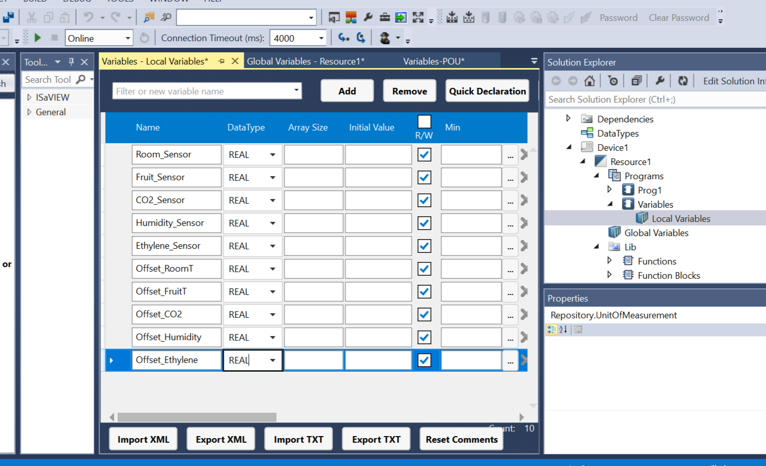
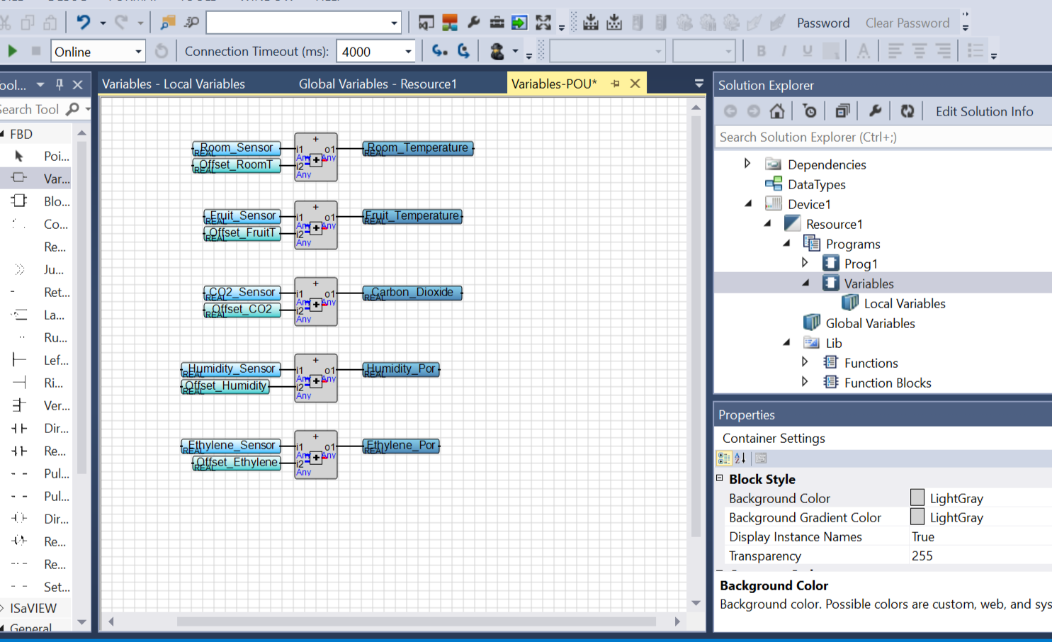
Variables
In this process, I have established critical variables – Room Temperature, Fruit Temperature, Carbon Dioxide, Humidity, and Ethylene – which are pivotal for the monitoring and control of the fruit ripening process. To ensure the accuracy of the sensor data, a crucial calibration step is executed using a summation gate. This gate effectively combines two real numbers, which are the sensor readings and an offset, with these variables being represented as 32-bit real-point numbers. The calibration process involves adding the offset to the raw sensor values using summation blocks. The program's structure incorporates multiple summation blocks for each variable, resulting in the generation of precise and finely-tuned values for temperature, carbon dioxide, humidity, and ethylene. This initial program setup serves as the cornerstone for the advanced control and monitoring of the fruit ripening process, where these calibrated variables are integrated into the control logic for seamless operation and optimization.
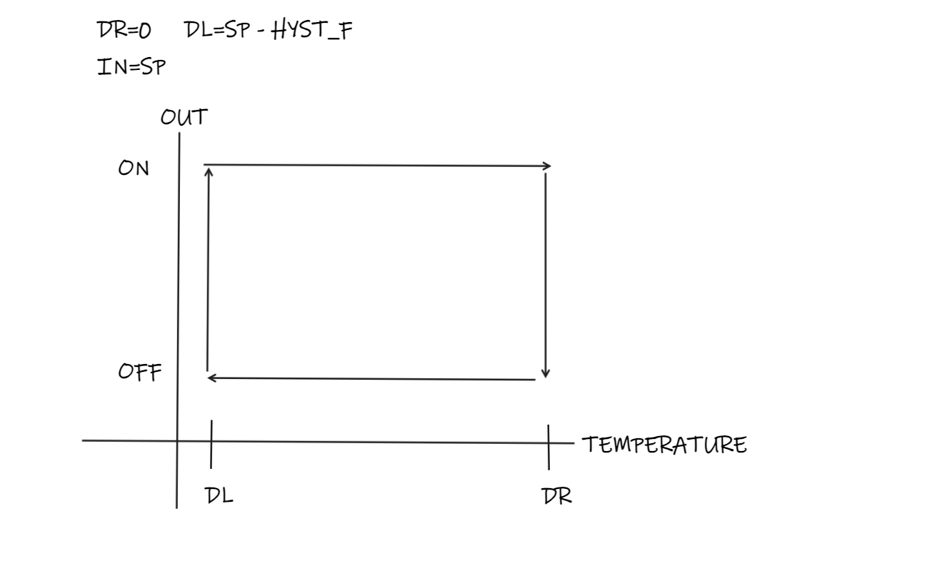
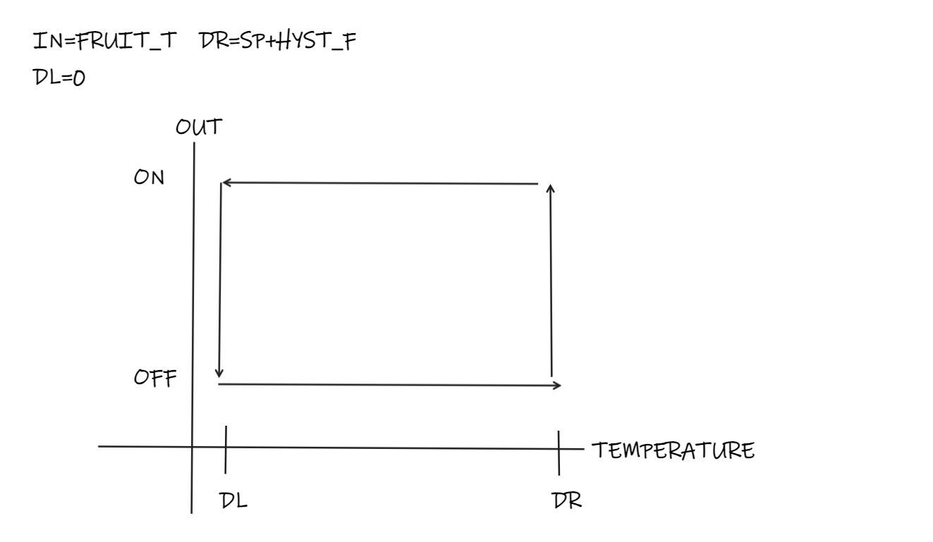
Hysteresis
Following the successful conversion of physical variables for the controller, the next step involves implementing the hysteresis process. This process defines a setpoint and compares it to the current value to determine the on/off state of a digital output. The comparison results in a '1' when a specific temperature threshold is reached, indicating output activation. When the temperature falls below a defined left differential threshold, the output is turned off. This enables the activation of devices like heaters. The process can be reversed by inverting the values or using a NOT gate. To manage the system, an "Enable" variable is introduced, which, when combined with the hysteresis output through an AND gate, exclusively activates the chiller when the system's temperature exceeds the setpoint and the system is enabled. This meticulous control ensures efficient temperature regulation.
Reverse
Code example in StructureText
IF(In>=SetP+DiffRight)
THEN Out:=TRUE XOR Reverse;
ELSIF(In<=SetP-DiffLeft)
THEN Out:=FALSE XOR Reverse;
END_IF;
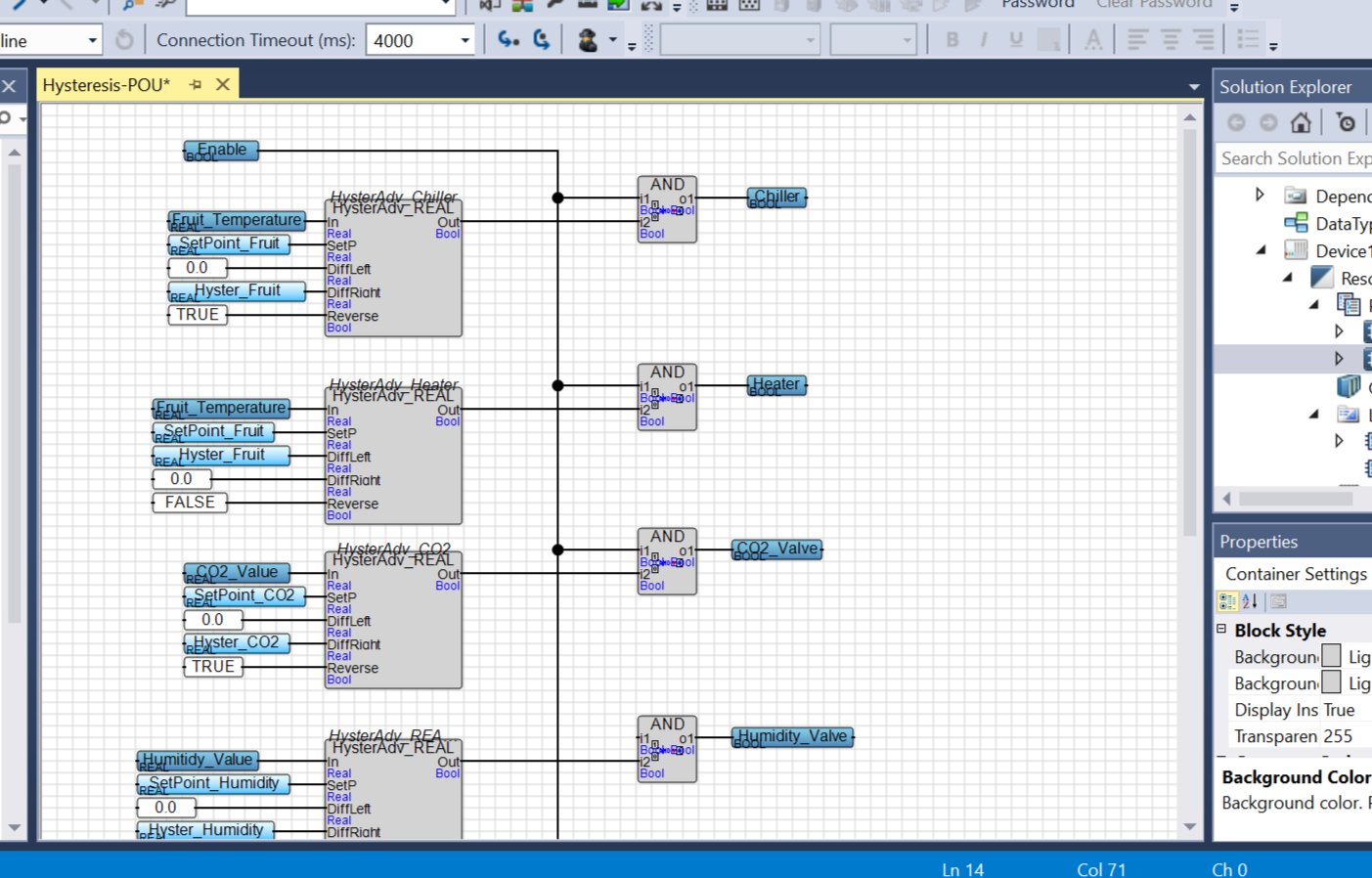
Activation trought hysteresis process
I create an "Enable" variable to activate the entire system. If the temperature comparison with the setpoint, using the hysteresis process, exceeds the setpoint, it triggers the activation of a chiller to initiate cooling. This is achieved through an AND gate that takes both the "Enable" variable and the hysteresis output as inputs. In summary, the chiller is activated only when the system's temperature surpasses the setpoint, and the entire system is enabled. This process of hysteresis blocks is applied to each variable, allowing for the activation of a heater, chiller, CO2 inlet valve, ethylene inlet valve, and humidity valve as needed for precise environmental control.